Protection and sequencer circuits
Protection of the amplifier
This page describes various circuits to protect the amplifier and sequence the relays used.
- PIC controlled protection and sequencer
- analogue protection and sequencer
- simple digital sequencer
PIC controlled protection and sequencer
A 16F84A PIC is used to control all relays and timers.
The following outputs are provided: The following inputs are provided:
high voltage supply on/off relay high voltage switch
G2 power supply on/off high voltage present detection
ptt driver PTT (switching to ground and 12V provided)
ptt PA hi / low power (use of driver stage only)
antenna relay antenna relay, confirmation switch "relay in tx position"
high Ia or Ig2 current detected
reset
12 Volt / PA switched on
Principle of operation
There are two situations with different sequences :
1) 12V present for rx/tx relay and pre-amp. Use of driver stage only. The PA is switched off.
2) The PA is switched on. The driver or driver + PA can be used.
In both cases the rx/tx relay is activated in the rx state. In the tx state the 12V to the relay is removed.
Sequence 1
In sequence 1 the PIC checks continously if the PTT is activated. As soon as the PTT switch is made the antenna relay is released to the tx state and the 12V to the pre-amp is removed. At the same time a delay is started. As soon as the antenna relay indicator switch (at the relay) provides a positive feedback of 12V, indicating the relay has been made, this delay ends. A second timer of 30 msec is started. This second delay allows the relay to settle (a heavy relay like the HF 5000 needs this additional delay) before the ptt of the driver stage is activated and rf is allowed to the antenna relay. This way it absolutely sure that no rf is switched while the antenna relay is still "bouncing". Burning of relay contacts is prevented.
As soon as PTT is released the ptt of the driver is released as well. The antenna relay is released with a 20 msec delay.
Sequence 2
In sequence 2 the circuits of the PA will be activated by throwing the 12 Volt PA switch. By throwing the 12V PA switch the fillament, blower, Grid 1 power supply, etc are powered as well. As soon as the 12V switch is thrown a 60 second delay is started, allowing proper warm-up of the QBL 5/3500 tube. During this 60 seconds delay sequence 1) can still be executed provided that the hi/low switch is in the "low" posistion. In case the switch is in the "high" position high voltage is required, which is not present yet. So PTT will be blocked.
As soon as the 60 seconds delay has expired the High Voltage power supply can be switched on. However this requires that the Reset switch is pushed first, indicating an "all clear" situation.. Activation of the Reset switch can be done any moment after switch-on of the 12V. In case the 60 seconds has expired the HV power supply will only switch on after Reset has been pushed.
Because the HV power supply has an internal 4 seconds voltage ramp-up a delay of 5 seconds is started after switch-on of HV, allowing the voltage ramp-up to finish without any PTT- or other interruptions. Of coarse the voltage ramp-up can be terminated instantly by deactivating the HV switch.
The G2 power supply is activated as soon as the HV power-up cycle is finished, HV is detected as being present and the "high" position is chosen. In case of a "low" position the G2 is not activated.
Depending on the setting of the hi/low switch either the driver or the driver + PA will be activated during PTT. The PTT sequence is the same as described at Sequence 1 with the addition of the switching of ptt PA. Ptt driver and ptt PA are activated and released at the same time.
Fault conditions and continuous checks
In case "high" is chosen, but HV is not activated (and consequently both HV and G2 not present) an incorrect combination is chosen and no PTT will be possible
During PTT it is constantly checked if the antenna relay indicator switch is still activated. In case the antenna relay indicator switch is no longer providing a positive feedback, the PTT cycle is interrupted and ptt-driver(, ptt PA if applicable) and antenna relay voltages are restored to the rx-state. This is applicable to both sequences.
Additionally in sequence 2 it is checked if high voltage is actually present in case the HV switch is on. In case no high voltage is detected, while the HV power supply is switched on a fault condition occurs and the switch-off sequence is started (see below).
In case an excessive Ia or Ig2 current is detected the switch-off sequence is started as well.
Switch-off sequence :
The following is switched of : ptt driver, ptt PA, G2 power supply and HV power supply. PTT is interrupted. The antenna relay returns to the rx state. After the automatic switch off a delay of 5 seconds prevents PTT.
After termination of a switch-off sequence pushing PTT will only activate sequence 1. Reset must be pushed to clear the "faulty" state and allow HV and G2 which are needed to activate PTT PA in sequence 2.
Only in case the 12V switch is deactivated the full 60 seconds delay will be applicable again. In other cases Reset and reactivation of the HV and G2 power supplies is possible after a 5 seconds delay. (At your own risk. Better check first what caused the automatic switch off)
Software
The PIC 16F84A software is contained in an .asm.file. This is the assembler listing. The assembler contains comments at each line in order to explain the progam flow. Both the sequence and timers can be set to any value needed. The .hex file is available here.
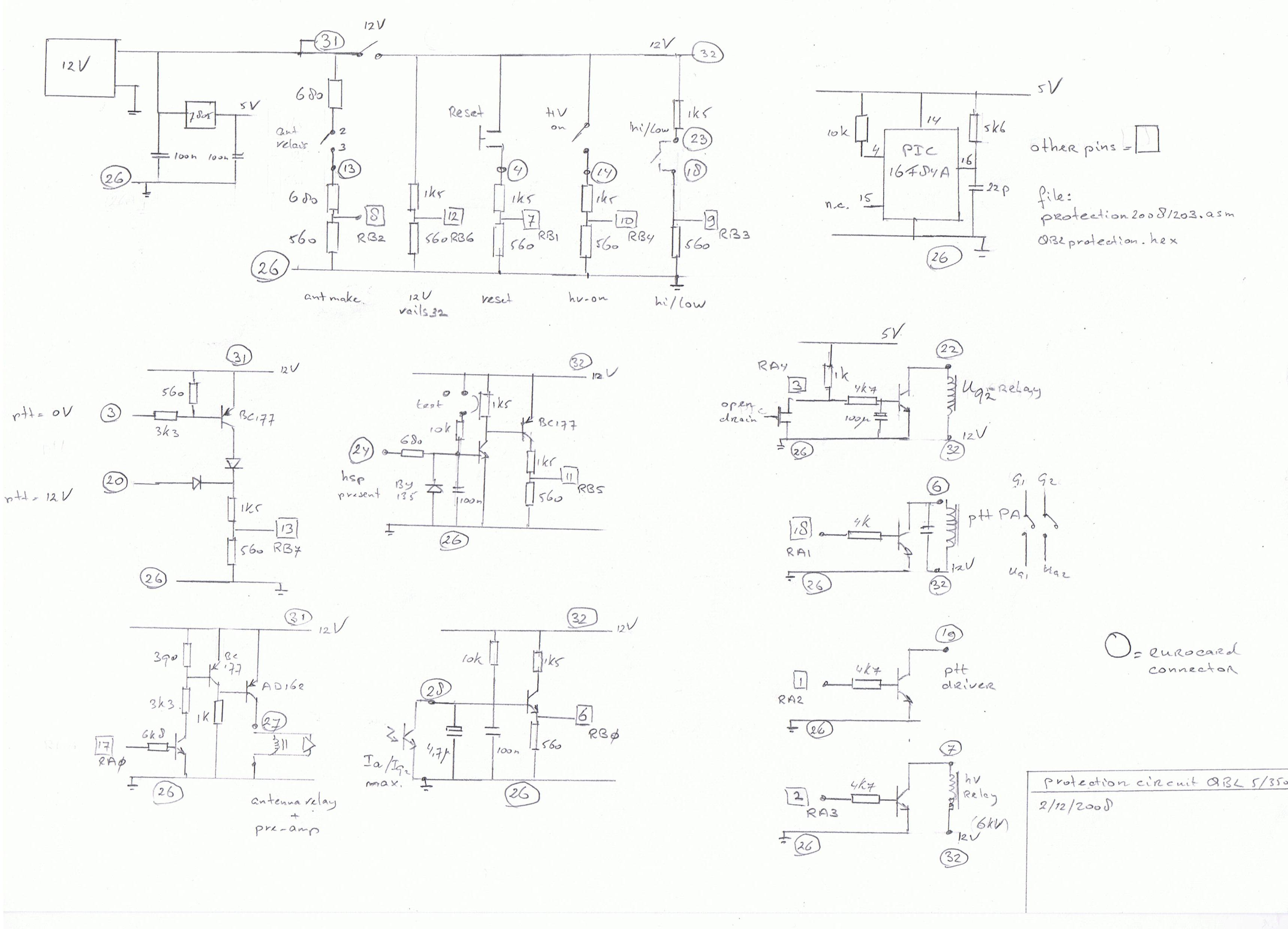
Hardware
The schematic below describes the necessary electronic circuits. It is self explanatory.
Analogue protection circuit
The analogue protection circuit is rather straight forward and uses the same principles as the PIC version. Both circuits are 100% compatible, built on an Eurocard and and interchangeable.
The principles are as follows :
After power-on approx. 60 sec PTT delay to allow proper heating of the tube.
Ug2 switching only when high voltage (Ua) is present and the antenna relay is in the tx position.
Detection of high current / flash-over (Ia and Ig2) and automatic switch-off of both the high voltage and screen voltage power supplies.
Interruption of PTT in case of trouble.
On-board RC-based sequencer (a digital version is described as well)
Protection circuit schematic
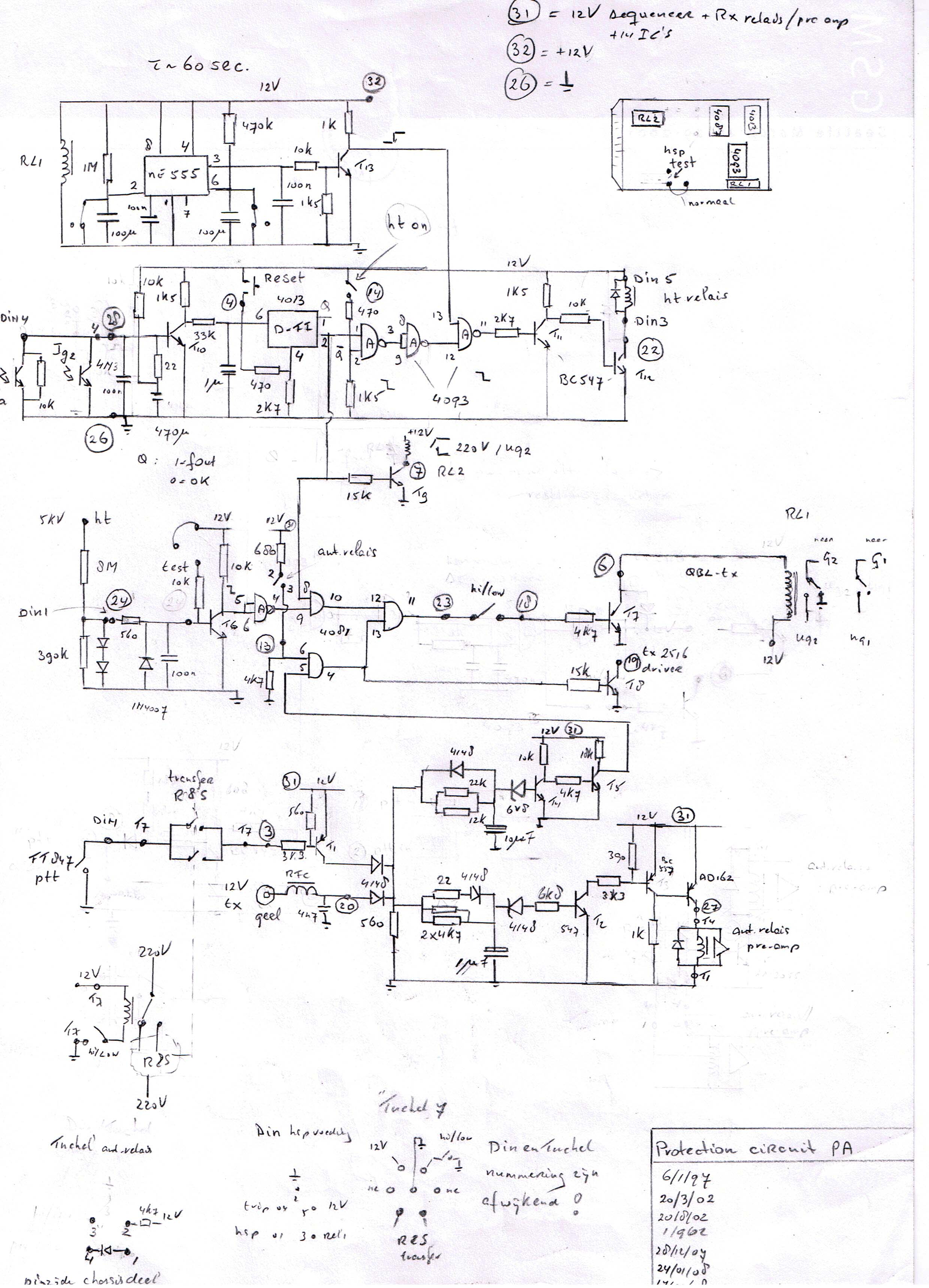
Description of the circuit
After power-on the 12 V DC is applied and the relay RL1 activates, allowing the timing capacitors around the NE555 to charge. The timer NE 555 starts its timing sequence. After approx. 60 sec. a positive voltage is available on pin 13 of the NAND-gate. As soon as the power is switched off the relay discharges the timer capacitors, ensuring a full 60 sec. delay again.
The 4013 D-Flip flop starts in a Q=1 state. A manual reset is necessary to allow Q-inverse to become positive. The following NAND combines the D flip flop output with the command "ht-on" from the switch. This signal is inverted and combined with the NE 555 timer signal.
In case the 60 sec. have expired AND the ht-on switch is set AND the D flip flop has been reset the high voltage will be switched on.
As soon as high voltage is detected a positive signal is send to a NAND gate to which the PTT signal is connected as well. In case high voltage AND the PTT signal are present AND the antenna relat has been switched to the tx state the Ug2 will be switched on.
The PTT signal could be negative (ground) or positive (+12V) going. Separate inputs are provided.
The driver will be switched on after the antenna relay has switched to the tx state, but disregards the state of the high voltage; allowing low power operation with just the driver as well..
In case excessive Ia current is detected a negative going pulse will be present on point 30. This voltage is derived of a 10 kV opto-coupler. (see power supplies for further details of the detection circuit). The pulse is amplified/inverted and will cause the D flip flop to change its state.
Not all the requirements to activate the ht-relay are met anymore so the high voltage will be switched off. Also the primary 220V of the Ug2 transformer will be switched off. At the same time the PTT to the amplifier is interrupted.
In case the Ig2 is more then 175 mA the D flip flop will be reset as well. The outputs of the opto-couplers are connected in parallel, both activating the same circuit.
The robustness of the circuit was tested the hard way. Several times a short circuit was caused in the anode compartment while all voltages were present. The damage inflicted was restricted to (sometimes) a blown fuse in all cases.
Digital sequencer (protection of the antenna relay and pre-amp)
Above an RC-based sequencer is used. As an alternative a digital sequencer could be used as well.
As soon as the sequence is started it simply continues, unrespectable of the position of the PTT switch.
Both sequencers have been used with good results.
Sequencer schematic

The circuit is quite simple and built around a 4024 counter. The activation of the PA is delayed by two time sequences in order to allow all relays to settle. As soon as the PTT switch is released the PA is deactivated as well. All other relays and pre-amp follow one time sequence later.
The sequence can be seen in the logical table above.
It is highly recommended to use a sequencer. High power will destroy relay contacts when they are "hot switched". Also the pre-amp may not survive open relay situations where rf could be present.